Sculptural surfaces for ship hull modeling become a industrial standart. What benefits we have got from it and what problems we can face.

Beginning
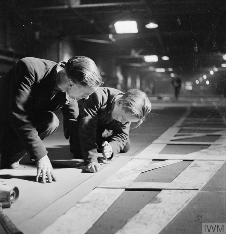
Now nobody can even imagine how to build ships without computers, especially the ship's hull. The huge army of loftsman's made hull drawings in real scale on mould loft in past. Every hull part, connected to hull surface, can be reproduced from this drawing. It was a hard job and loftsman was very important persons on the shipyard. The most useful tool was the spline. Bended spline goes through a set of points, helps loftsman draw a smooth line. It can be frame section or any other line in connection to hull surface.

Base on the spline, goes through a set of points, loftsman draw a smooth line. It can be frame section or any other line in connection to hull surface. Experienced loftsman new a lot of tricks on how to make his work easy.

First experiments with computers
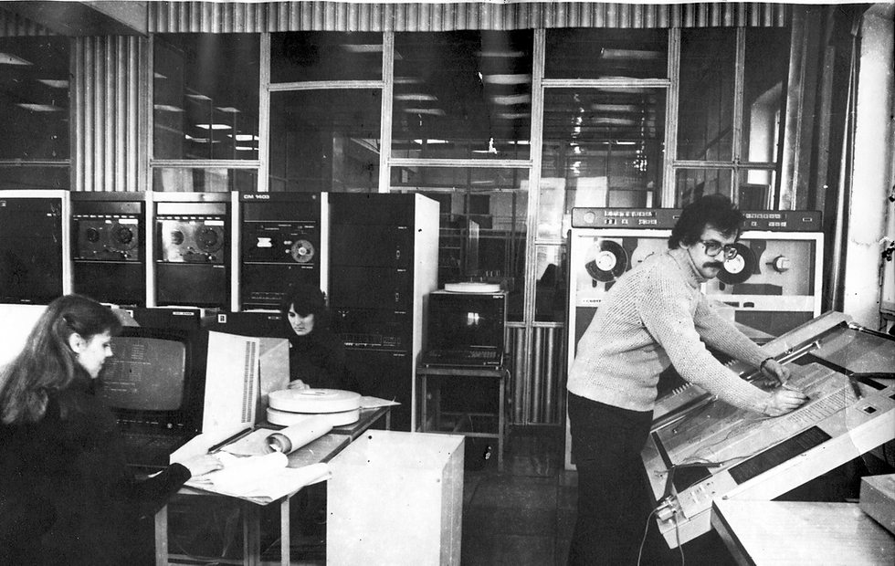
Computers change our lives and sometimes it happens quickly and dramatically. Probably, many already do not remember huge offices of design bureau with hundreds of drawing tables and army of draftsmen. The profession of the draftsman has disappeared from our lives forever with the advent of AutoCAD. CAD systems have essentially become a means of expressing engineering thought and have completely replaced pencils and rulers. In the last ten years, even paper copies of drawings have disappeared. The design process has greatly accelerated and has been improved. With using CAD systems even small teams can carry out large engineering projects.

Ships, as well as aeroplanes and cars, have always been one of the toughest engineering objects. These industries before others began to use CAD systems, as it gave a significant reduction in terms of the design of objects and cheaper design process.
Pierre Bezier pioner in parametric lines and surface in CAD design.
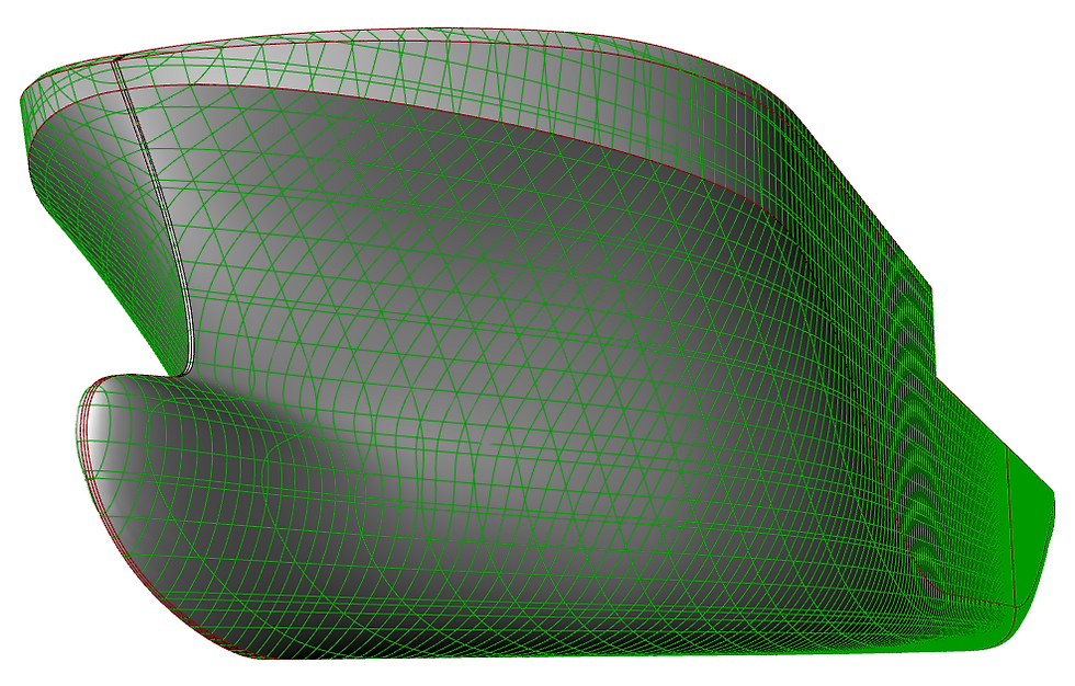
In the mid-sixties of the last century, Pierre Bezier was one of the first to suggest using a parametric representation of curves and surfaces for geometric modelling. The tool of control of the shape of curves and surfaces offered by him by changing the position of control points was simple and convenient. Curves and surfaces Bezier have become so popular with designers that at present almost any CAD System uses them in its toolkit. Parametric representation Bezier - B-Spline - NURBS Curves and surfaces has long been a de facto standard for modelling and information exchange 3D Objects of complex geometric shape. By other words, this type of surfaces calls sculptural surfaces. Sculptural surfaces are used in the design of objects whose surfaces cannot be modelling only by the fragments of surfaces of cylinders, cones or spheres. In fact, this title is the very essence of such a design process. As a sculptor, creates an image, removing all superfluous and constructor, changing the position of the control points of curves and surfaces trying to achieve the required shape.

What benefits we have by using sculptural surfaces
Sculptural surfaces have many advantages over other design methods. Here are just a few of them:
-Parametric representation gives Possibility Descriptions of almost any form,
-Simple and intuitive for the designer apparatus change the shape of the surface,
-analytical representation, allowing to calculate coordinates of any point on a surface within a site,
-The possibility of analytical calculation of geometrical characteristics of a surface within a site, such as lines of inflexion and curvature,
-Possibility to transfer the surface model to another CAD System without distortion and the necessity of additional approximation and re-smoothing,
-performance of the specified conditions of smoothness of a surface within one site and possibility of analytical joining of sections of surfaces on borders.
What problems we meet with sculptural surfaces
However, there are several difficulties encountered in dealing with these surfaces:
-The process of surface modification causes difficulties for novice users,
-The result is highly dependent on the splitting of the hull surface into areas
-Modeling requires knowledge of geometrical properties of curves and surfaces of this type,
-unlike models where the surface is defined by a set of lines that can be modified, in the case of sculptural Surface Lines are the result of section construction and cannot be changed directly.
With the appearance of sculptural surfaces in the development of programs for smoothing the ship's surface ended the stage of experiments, which lasted without a small half-century. Currently, most programs use, in some form or another, NURBS surface. It would seem that all the problems of smoothing the ship's surface have already been solved and there is no need to return to it again and again.
In fact, it is the same tool as once a spline, and it also requires certain skills and knowledge for correct use. We have only automated the routine operations used in surface modeling. The modeling of sculptural surfaces is a creative process and does not apply to such operations.

Comments