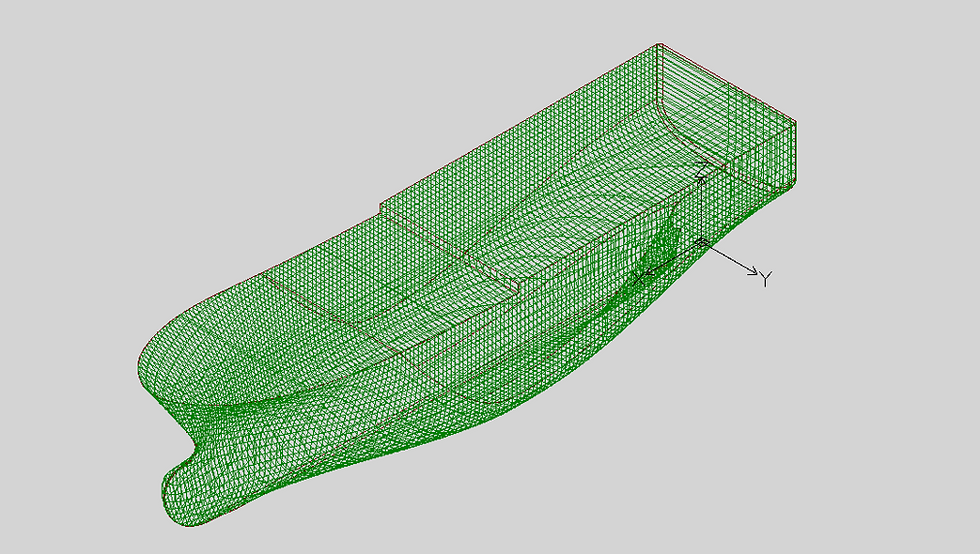
Shape Maker CAD export files.
- Alexander Alexanov
- Feb 28, 2020
- 3 min read
Updated: Oct 9, 2020

In the Shape Maker system, there are several different options for presenting output documents that represent the surface of a ship. Depending on the technology of designing and issuing working documentation used by the design company, various options for representing the ship's surface can be used. Consider the main options for using the output documentation. The output documentation can be divided into three groups: a three-dimensional model, two-dimensional drawings, and text and binary information exchange files.
Three-dimensional model.
The three-dimensional model can be represented as IGES and DXF files. The IGES file contains a mathematical description of the lines and surfaces describing the model of the ship's hull. This representation allows you to transfer the model to other systems is absolutely identical. That is, the model is transmitted with absolute accuracy. Such a model can be used, for example, to transfer the surface to systems for the production of working documentation. The information transmitted to IGES is a collection of cropped and uncut sections of NURBS surfaces and NURBS curves. It is important to note that the transmitted geometry in fact does not contain a set of points of a line or surface grids, but mathematical coefficients and parameters by which any point on curves or surfaces can be calculated.

A DXF file contains a three-dimensional representation of a surface given by a set of cross-sections and three-dimensional wireframe surface lines. Additionally, the surface can be represented as a grid of contours (mesh). This output option is not absolutely accurate, although the lines are represented with an accuracy of 0.1 mm by default. Sometimes this representation is used to build presentation models, especially grids can be used to create realistic representations of the object. It can also be used to enter data into systems importing a set of cross sections, for example, for calculating hydrostatics. The three-dimensional representation of the cross sections of the body is convenient to use to manually perform geometric constructions in AutoCAD. For example, the construction of a line of intersection of two surfaces defined by a set of cross sections.


For the convenience of working with model elements, section lines and grids are spaced at different levels of the DXF file. The accuracy of the transfer of surface grids is set when the model is exported from the system. Additional information about data exchange you can find here.
Two-dimensional drawings.
Much more options for outputting two-dimensional drawings as DXF files. The simplest is to display a copy of the screen. All information on the screen is copied to a file in the same perspective as the model looks on the screen. This is convenient for quickly obtaining a two-dimensional image of the three-dimensional model.

The most common conclusion is a lines drawing with stations and building frames. It is possible to derive both one of the projections and a whole drawing of three projections. The drawing is also in 2D.
The system also provides the output of cross-sections into separate files. This option allows you to use section files as blocks when making drawings of the hull structure and General Arrangement in AutoCAD.
For the same purpose, the projection of lines into separate files is used. For example, projections of the lines of decks.


The shell expansion drawing, with the positioning of all hull shape lines, can also be output to a DXF file. Shell expansion drawing is quite laborious if done manually. When making the shell expansion drawing in Shape Maker, all lines connected to outer surface will be reflected in this drawing. You can specify deck lines, knuckle lines, side contour lines, and other lines. Despite the conventionality of the image of this drawing, it is still used and is very informative.

Text and binary files.
The system also provides several text and binary files for transferring information to the calculation modules. For example, the ASF file is a text copy of the project database and can be used to transfer the model to other programs. The STC file is used to transfer data for hydrostatic calculations. This file is binary. As an example of a text file, you can use the Offset table file, which is automatically generated based on the source data for the location of frames, water lines and buttocks. The book is issued Part 1, Section hull and Part 2, Information about the position of the main frame lines, seams and butts, decks lines, platforms, bulkheads and a set.


Comments